In Project 11 we were introduced to the power of Node Red’s graphical interface and the Raspberry Pi. In this project we will see how we can use Node Red to obtain data from an Arduino connected to the Pi through its serial interface.
Arduino Preparation
We are going to revisit the Arduino Project 11 and set it up to measure temperature and humidity.
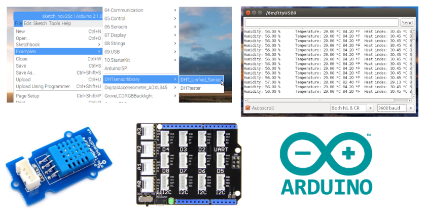
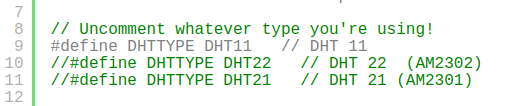
Setting up the Arduino should be a review; do not forget to comment out the other DHT sensors and uncomment the DHT11. Plug the sensor into the Grove shield’s A0 port.
Go ahead and run the sketch and open the serial monitor to see the temperature and humidity readings scrolling down the display. When you are satisfied it is working close the Arduino IDE.
Get Node Red Running
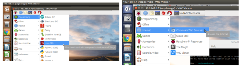
Open Node Red, leave the Node Red console open and then open your Chromium browser. In the search window type in ‘raspberrypi.local:1880
Build Your Flow
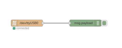
Pull the Serial Input node and the Debug node onto your workspace.
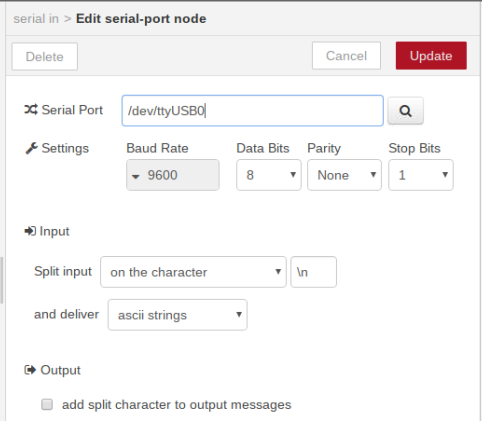
Edit the serial input to match the serial output from the Arduino: 9600 baud and /dev/ttyUSB0; then connect the 2 nodes by pulling a wire from one to the other.
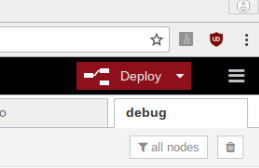
Deploy the sketch. Click on the Debug tab on the right-hand side to display debug messages.
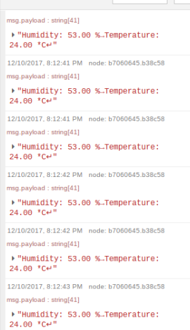
The Arduino’s humidity and temperature messages should be scrolling down the display. Anything that can be sent to the serial monitor can also be viewed this way; just not at the same time: only one application can hold the serial port at a time.
Keyboard Flow
Click on each node on your work surface and hit the delete key until it is empty again.
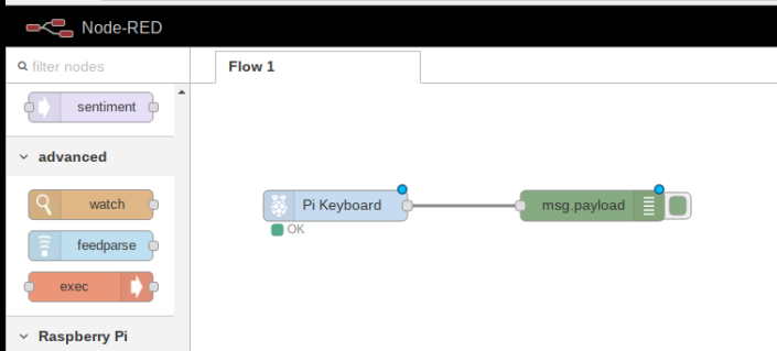
Click and drag Pi Keyboard and Debug nodes onto your workspace and connect them.
Deploy the flow and observe the debug window while hitting the up, down, left and right keys:
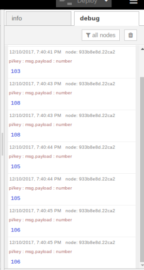
Every key has a code. What I got from that is up is 103, down 108, left 105 and right 106. Let us use these codes to control some LEDs.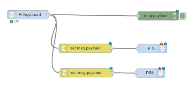
Pull 2 Change nodes and 2 Pi GPIO output nodes onto your work area and wire them as illustrated above.
Edit the Change Nodes
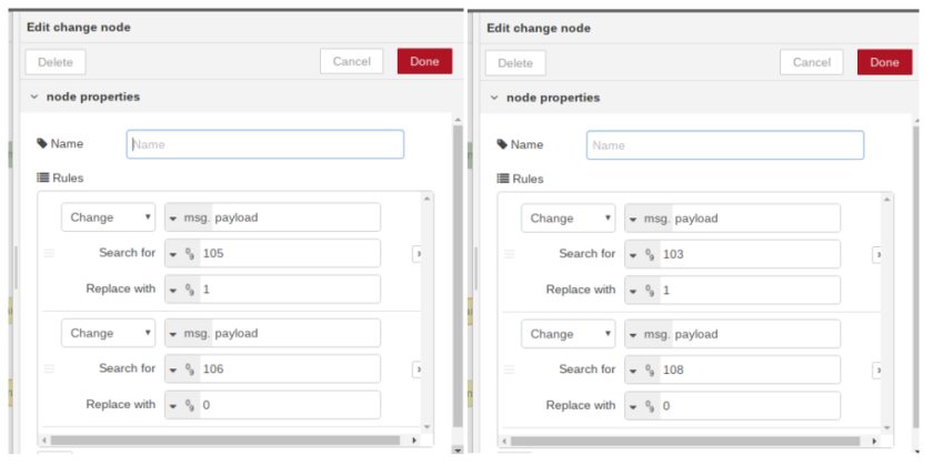
Edit one node with the up and down key numbers and the other with the left and right.
Edit the Pi GPIO Outputs
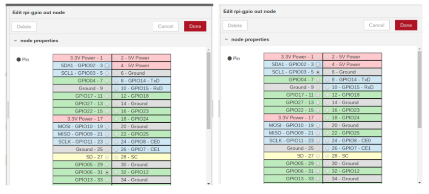
Edit the 2 Pi GPIO output nodes by setting one to GPIO 6 and the other to GPIO 3.
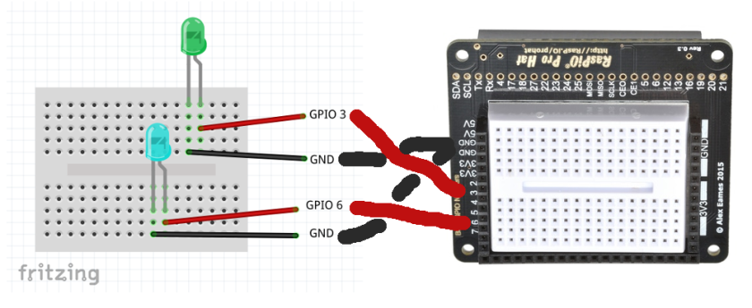
Deploy the flow. Now try pressing the keyboard’s up, down, left and right buttons. Up should turn on one LED and down should turn it off; left and right should turn the other on and off.
Do This At Home

Sketch out how many buttons and which keys would you use to control a robot.
