This project explores adding analog-to-digital conversion to the Raspberry Pi.

The Raspberry Pi can natively do a lot of great things; but it is unable to measure an analog signal.
Signal Types
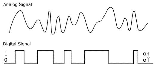
The 2 broad categories of signal types are analog and digital. Nature is full of analog signals that are characterized by continuously varying levels of amplitude and frequency. Animal noises, human speech and music, radio noise from the Sun and distant stars are all analog. Digital signals are generally binary: 1 or 0; on or off; true or false. In order for a computer to process analog signals analog-to-digital (A/D) converters are necessary.
Sampling Rate
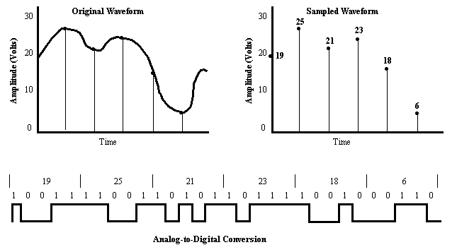
A/D conversion takes samples of an analog signal at different points in time and outputs a digital representation of its amplitude. The Nyquist frequency is the minimum rate at which a signal can be sampled without introducing errors, which is twice the highest frequency present in the signal. In other words, A/D conversion of a phone conversation (300Hz to 3KHz) would have to be sampled at 6000 times per second to accurately capture and reproduce it. Music (20Hz to 20KHz) would require on the order of 40,000 samples per second. On the other hand, if you are measuring something that changes slowly, like temperature; a reading every 5 minutes may be sufficient.
MCP3008 A/D Converter
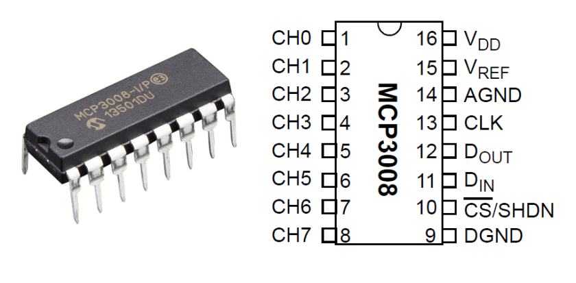
The MCP3008 is a 8 channel 10-bit analog to digital converter. The 8 channels means it can be used to monitor 8 different analog signals simultaneously; the 10-bits means that its resolution differentiates between 0000000000 and 1111111111 (0 to 1023). Since we will be powering this A/D with 3.3V from the Raspberry Pi the smallest change in voltage it can detect is 3.3V/1023 = .003V or 3mV resolution.
TMP36 Analog Centigrade Temperature Sensor
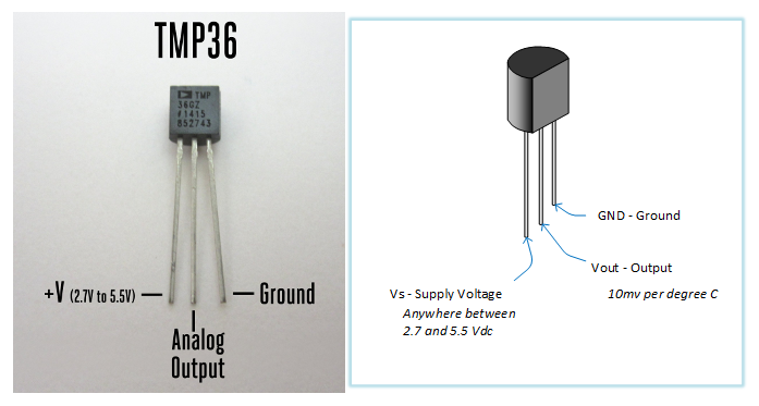
In order to give us something analog to measure, we are going to use the TMP36 precision Centigrade temperature sensor. It functions like a zener diode that breaks down at a voltage that reflects the temperature at 10mV per degree. This makes it very easy to interpret: 250mV corresponds to 25 degrees C (just move the decimal point 1 to the left).
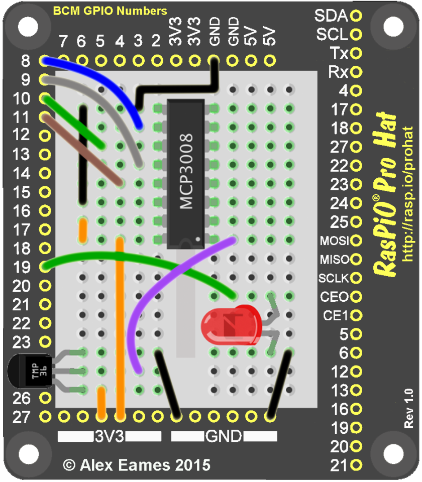
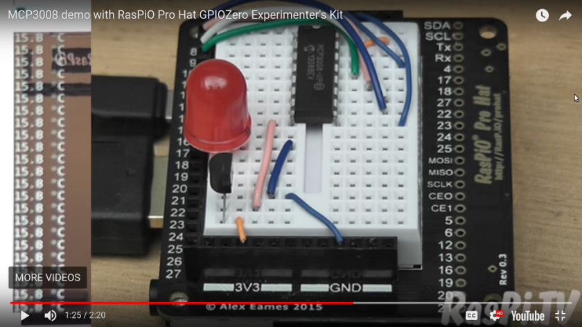
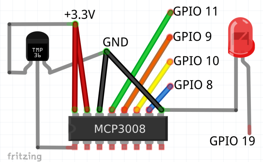
Wire the circuit as pictured. You do not have to use the same colors of wire; the only 2 critical things is to get the TMP36 oriented correctly (rounded end to the rear) and the notch on the MCP3008 as shown. Either one could be damaged it they are put in backwards. The drawing below is another rendering of the circuit:

Always double-check your wiring; if you have someone with you have them check. (Touch the TMP36; if it is hot; pull it out! It is wired backwards.)
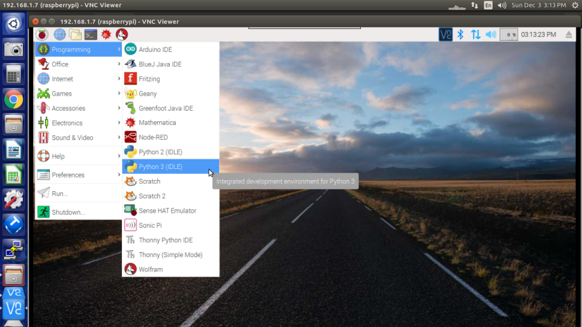
Open Python 3 (IDLE) editor.
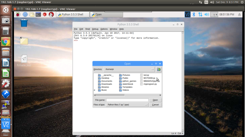
Open MCP3008.py
from gpiozero import MCP3008, LED
from time import sleep
deg = chr(176)+'C'
tmp = MCP3008(channel=0, device=0)
red = LED(19)

while True:
    temperature = (tmp.value * 3.3 - 0.5)*100
    if temperature >24:
        red.on()
    else:
        red.off()
    print('{:.1f}'.format(temperature), deg, 10 * ' ')
    sleep(0.1)

############
#  This would show you the voltage from the TMP36
#    print(tmp.value * 3.3, " V")   # Voltage
#  This would show you the temperature to lots of dp
#    print((tmp.value * 3.3 - 0.5)*100, " C ")
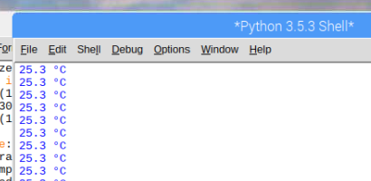
Run the code. You should see temperature readings. Touch the TMP36 sensor and see it go up a little.
Do This At Home

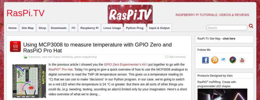
Visit the RasPi.TV Website and check out their video.
http://raspi.tv/2016/using-mcp3008-to-measure-temperature-with-gpio-zero-and-raspio-pro-hat

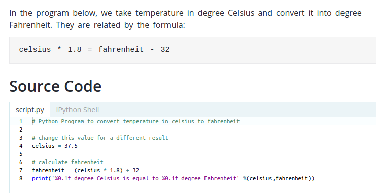
Try editing the code to read Fahrenfeit:
m
